According to repair biz iFixit, the issue with the power-frugal LPDDR memory chips is that the lower voltage they operate at calls for more attention to be paid to signal integrity between the CPU and memory. In practice, this has meant shorter track distances on the circuit board, leading to LPDDR being soldered down as close to the processor as possible.
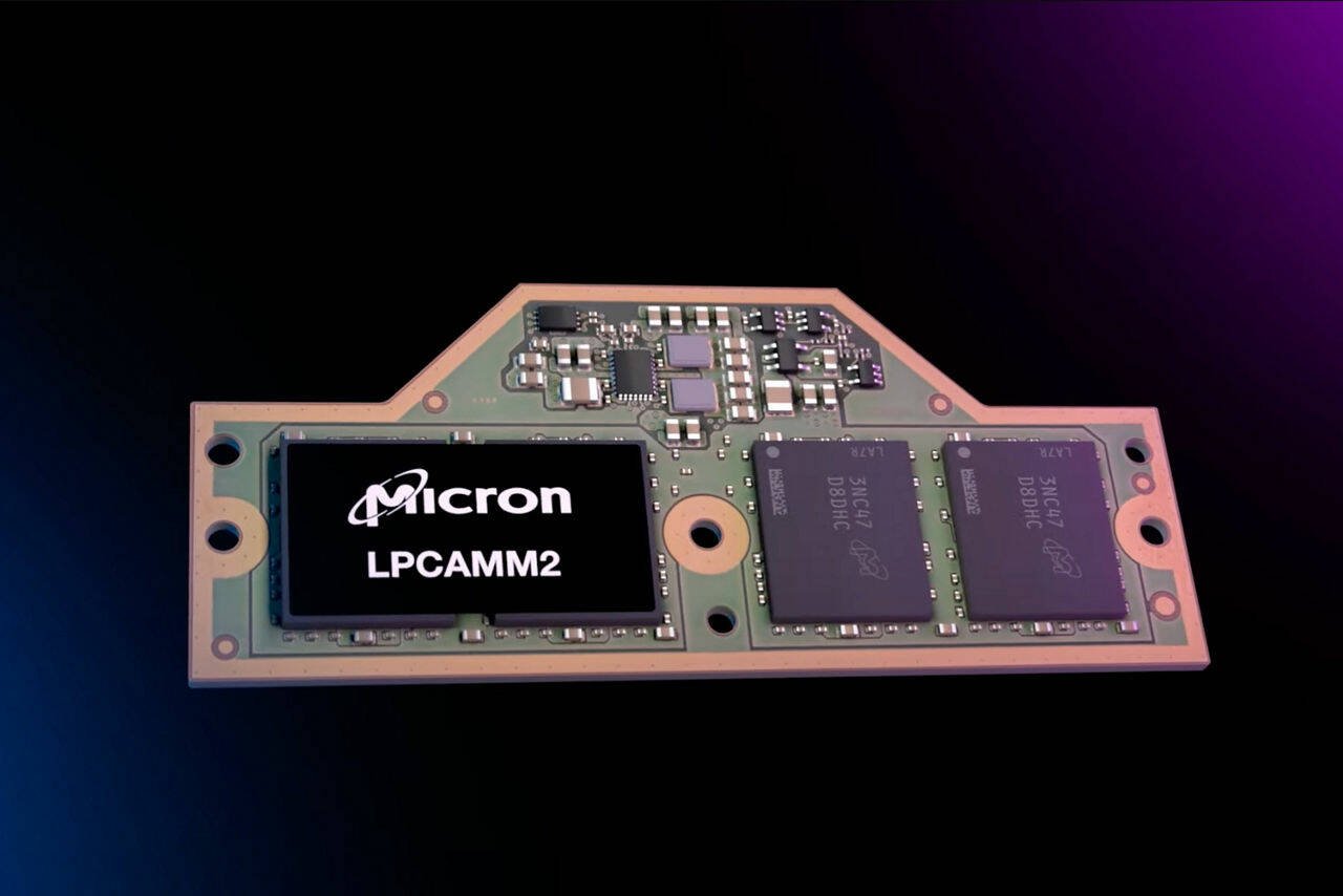
LPCAMM2 is intended to address this by putting LPDDR onto a circuit board module that is “cleverly designed to mount right up next to the CPU,” with “very short traces to help maximize signal integrity,” the iFixit team explains in a blog and video detailing their hands-on with the ThinkPad P1 Gen 7.
the lower voltage they operate at calls for more attention to be paid to signal integrity between the CPU and memory
And they aren’t kidding around, modern high speed signals are so fast that a millimeter or less of difference in length between two traces might be enough to cause the signals to arrive at the other end with enough time skew to corrupt the data.
Edit: if you ever looked closely at a circuit board and seen strange, squiggly traces that are shaped like that for seemingly no reason, it’s done so that the lengths can be matched with other traces.
USB3 is quite forgiving regarding the layout. The standard ±10% impedance matching is fine, and because there is no dedicated clock line you don’t need to do length matching either. Even differential pair length mismatch is not that big of a deal. If 0.1mm is easy to archive, sure go for it, but I’d rather compromise on this in favor of more important parameters.
So, does it just have really advanced error checking? How does it handle the mismatches? I believe you, it’s just that the phrase “not that big of a deal” is doing a lot of heavy lifting here.
The signal does not care about how it gets from the sender to the receiver. The only thing that matters is that at the receivers end 0s and 1s can be separated. One common measurement is the eye pattern. If the eye is “open” enough (=matches the spec), communication is possible.
Impedance mismatch causes reflections (visible as oscillation after rising/falling edge), differential pair line mismatch degrades the slop of the signal transition (rising/falling edge). Geometric features only matter if they are large compared to the signal wavelength. As a rule of thumb features smaller then 1/20th of a wavelength can be safely ignored, often times a ratio as large as 1/5 works just fine. USB3 uses 2.5Ghz (5Gbit/s) or 5Ghz (10Gbit/s), where 1/20th result in 3.4mm and 1.7mm respectively (assuming an effective dialectic of 3.17). This is still grossly simplified, because in many real systems you don’t control the entire transmission line (eg. user buys a random cable and expects it to work), so it makes sense that the USB consortium specifies eye patterns and factors in various system uncertainties.
RAM on the other hand uses 16/32/64/128 single ended data lines, with a dedicated clock line. Data does not have to arrive perfectly at the same time, but the margin may be as little as 1/10th of a clock cycle. Here accurate length matching is absolutely required. Its also the reason why the same CPU + RAM combination may archive higher stable clock rates on some mainboards then on others.
Ok, wow. Thank you for educating me on a great deal I didn’t know when I asked the question. And while it does a great deal to bridge that gap… the question remains unanswered: how is this breakthrough achieved?
Same, but now I’m working on very high-speed stuff for work and starting to get into that hobby-wise as well. Just yesterday had a conversation with a colleague about how things are getting too small to hand-solder.
My dedicated AI machine uses 1866mhz DDR3. Consumers don’t know what they need and will buy whatever the latest new thing is. Smart phones are so dumb. Like wow, your brand new $2500 phone has a benchmark 4x faster than my refurbished $250 phone. Now tell me what you do with all that power. “…well I save 27ms per Instagram post which adds up with how much I use it”. I want to run headfirst into a brick wall.
A couple old metrology equipment dated back from the 80s I still use calls them ‘mil’. It’s got dual dials for mil/mm. Gets me confused sometimes because the gauge can go down to couple millionths of an inch/couple 10s of nanometers.
Yeah, I’ve never heard of that before either. What I have heard of is either MOA or MIL reticles. In that context a Mil stands for milliradian, which is a representation of angle. That definitely doesn’t track with the post though.
And it’s especially confusing for people who use sane measurement systems where “mil” is short for “millimetre”, because it’s just the start of the word. I think anyone that still insists on measuring things in thousandths of an inch should keep their own bespoke lingo too, and everyone else should steadfastly refuse to acknowledge “mil” in this context.
In the design and manufacture of PCBs (aka circuit boards) a “mil” is a one thousandth of an inch, so it makes sense that’s what is being used in this context.
Also the maths check out: 0.005 inches is equal to aprox 0.12mm, “just over 0.1mm”.
Yeah, I found it wierd too when I started designing PCBs (as hobby) that “mill” actually stood for thousanth of an inch.
Probably for historical reasons, there are tons of things in the older domains within electronics that are based on inches rather than metric units: for example the spacing between the legs of a microchip in the older chip package formats (so called DIP, the ones with legs that go into holes) is exactly 0.1"
The sizes in more modern electronics isn’t usually based on inches anymore, but circuit boards are old tech (even if done with new materials) so there are still a number of measures in there which are based on inches.

For the curious (and lazy):
And they aren’t kidding around, modern high speed signals are so fast that a millimeter or less of difference in length between two traces might be enough to cause the signals to arrive at the other end with enough time skew to corrupt the data.
Edit: if you ever looked closely at a circuit board and seen strange, squiggly traces that are shaped like that for seemingly no reason, it’s done so that the lengths can be matched with other traces.
A millimeter is huge in these situations. USB3 requires 5 mil tolerances, just over 0.1 mm. This scales with the inverse of data rate.
Electronics are so fast that we gotta take the speed of light into account. God help you if you put too sharp a bend in a trace, too …
USB3 is quite forgiving regarding the layout. The standard ±10% impedance matching is fine, and because there is no dedicated clock line you don’t need to do length matching either. Even differential pair length mismatch is not that big of a deal. If 0.1mm is easy to archive, sure go for it, but I’d rather compromise on this in favor of more important parameters.
So, does it just have really advanced error checking? How does it handle the mismatches? I believe you, it’s just that the phrase “not that big of a deal” is doing a lot of heavy lifting here.
The signal does not care about how it gets from the sender to the receiver. The only thing that matters is that at the receivers end 0s and 1s can be separated. One common measurement is the eye pattern. If the eye is “open” enough (=matches the spec), communication is possible.
Impedance mismatch causes reflections (visible as oscillation after rising/falling edge), differential pair line mismatch degrades the slop of the signal transition (rising/falling edge). Geometric features only matter if they are large compared to the signal wavelength. As a rule of thumb features smaller then 1/20th of a wavelength can be safely ignored, often times a ratio as large as 1/5 works just fine. USB3 uses 2.5Ghz (5Gbit/s) or 5Ghz (10Gbit/s), where 1/20th result in 3.4mm and 1.7mm respectively (assuming an effective dialectic of 3.17). This is still grossly simplified, because in many real systems you don’t control the entire transmission line (eg. user buys a random cable and expects it to work), so it makes sense that the USB consortium specifies eye patterns and factors in various system uncertainties.
RAM on the other hand uses 16/32/64/128 single ended data lines, with a dedicated clock line. Data does not have to arrive perfectly at the same time, but the margin may be as little as 1/10th of a clock cycle. Here accurate length matching is absolutely required. Its also the reason why the same CPU + RAM combination may archive higher stable clock rates on some mainboards then on others.
Ok, wow. Thank you for educating me on a great deal I didn’t know when I asked the question. And while it does a great deal to bridge that gap… the question remains unanswered: how is this breakthrough achieved?
Which breakthrough do you mean? Can you rephrase your question?
That’s why serial busses won over parallel ones I guess.
Haha, I’m still over here messing with 10/100 Ethernet and USB 2 on my home projects. I’m used to bigger tolerances than the truly high tech stuff.
Same, but now I’m working on very high-speed stuff for work and starting to get into that hobby-wise as well. Just yesterday had a conversation with a colleague about how things are getting too small to hand-solder.
My dedicated AI machine uses 1866mhz DDR3. Consumers don’t know what they need and will buy whatever the latest new thing is. Smart phones are so dumb. Like wow, your brand new $2500 phone has a benchmark 4x faster than my refurbished $250 phone. Now tell me what you do with all that power. “…well I save 27ms per Instagram post which adds up with how much I use it”. I want to run headfirst into a brick wall.
I meant PCBs. I design custom circuit boards.
Like this one: https://www.tindie.com/products/bmoreautomation/esp-r8-poe-3c-automation-controller/
What is a mil in this context? I’m genuinely curious.
Probably one thousandth of an inch.
Ew.
Yes.
Hey thousands of an inch are the only part of our imperial system that actually makes sense
I’ve heard it referred to as ‘thou’ but not ‘mil’
A couple old metrology equipment dated back from the 80s I still use calls them ‘mil’. It’s got dual dials for mil/mm. Gets me confused sometimes because the gauge can go down to couple millionths of an inch/couple 10s of nanometers.
LVDT for those curious.
Yeah, I’ve never heard of that before either. What I have heard of is either MOA or MIL reticles. In that context a Mil stands for milliradian, which is a representation of angle. That definitely doesn’t track with the post though.
And it’s especially confusing for people who use sane measurement systems where “mil” is short for “millimetre”, because it’s just the start of the word. I think anyone that still insists on measuring things in thousandths of an inch should keep their own bespoke lingo too, and everyone else should steadfastly refuse to acknowledge “mil” in this context.
Correct.
A millimeter i.e a thousands of a meter.
edit: I was wrong, confusingly enough it is a thousands of an inch
5 mm isn’t ‘just over 0.1 mm’. That can’t be right.
Well, it depends on your margin of error.
In the design and manufacture of PCBs (aka circuit boards) a “mil” is a one thousandth of an inch, so it makes sense that’s what is being used in this context.
Also the maths check out: 0.005 inches is equal to aprox 0.12mm, “just over 0.1mm”.
I stand corrected, and I see I didn’t read the comment thoroughly enough either.
Colloquially as a non-pcb maker I would use and hear the term “mill” as short form millimeter so I assumed it was that.
so TIL :)
Yeah, I found it wierd too when I started designing PCBs (as hobby) that “mill” actually stood for thousanth of an inch.
Probably for historical reasons, there are tons of things in the older domains within electronics that are based on inches rather than metric units: for example the spacing between the legs of a microchip in the older chip package formats (so called DIP, the ones with legs that go into holes) is exactly 0.1"
The sizes in more modern electronics isn’t usually based on inches anymore, but circuit boards are old tech (even if done with new materials) so there are still a number of measures in there which are based on inches.
That inverse square law will fuck you every time