USB3 is quite forgiving regarding the layout. The standard ±10% impedance matching is fine, and because there is no dedicated clock line you don’t need to do length matching either. Even differential pair length mismatch is not that big of a deal. If 0.1mm is easy to archive, sure go for it, but I’d rather compromise on this in favor of more important parameters.
So, does it just have really advanced error checking? How does it handle the mismatches? I believe you, it’s just that the phrase “not that big of a deal” is doing a lot of heavy lifting here.
The signal does not care about how it gets from the sender to the receiver. The only thing that matters is that at the receivers end 0s and 1s can be separated. One common measurement is the eye pattern. If the eye is “open” enough (=matches the spec), communication is possible.
Impedance mismatch causes reflections (visible as oscillation after rising/falling edge), differential pair line mismatch degrades the slop of the signal transition (rising/falling edge). Geometric features only matter if they are large compared to the signal wavelength. As a rule of thumb features smaller then 1/20th of a wavelength can be safely ignored, often times a ratio as large as 1/5 works just fine. USB3 uses 2.5Ghz (5Gbit/s) or 5Ghz (10Gbit/s), where 1/20th result in 3.4mm and 1.7mm respectively (assuming an effective dialectic of 3.17). This is still grossly simplified, because in many real systems you don’t control the entire transmission line (eg. user buys a random cable and expects it to work), so it makes sense that the USB consortium specifies eye patterns and factors in various system uncertainties.
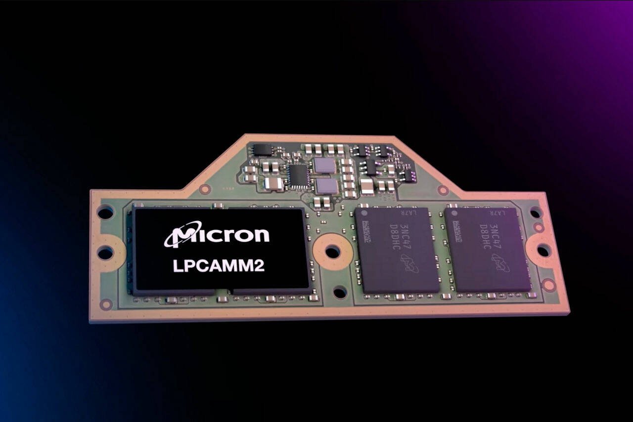
RAM on the other hand uses 16/32/64/128 single ended data lines, with a dedicated clock line. Data does not have to arrive perfectly at the same time, but the margin may be as little as 1/10th of a clock cycle. Here accurate length matching is absolutely required. Its also the reason why the same CPU + RAM combination may archive higher stable clock rates on some mainboards then on others.
Ok, wow. Thank you for educating me on a great deal I didn’t know when I asked the question. And while it does a great deal to bridge that gap… the question remains unanswered: how is this breakthrough achieved?
USB3 is quite forgiving regarding the layout. The standard ±10% impedance matching is fine, and because there is no dedicated clock line you don’t need to do length matching either. Even differential pair length mismatch is not that big of a deal. If 0.1mm is easy to archive, sure go for it, but I’d rather compromise on this in favor of more important parameters.
So, does it just have really advanced error checking? How does it handle the mismatches? I believe you, it’s just that the phrase “not that big of a deal” is doing a lot of heavy lifting here.
The signal does not care about how it gets from the sender to the receiver. The only thing that matters is that at the receivers end 0s and 1s can be separated. One common measurement is the eye pattern. If the eye is “open” enough (=matches the spec), communication is possible.
Impedance mismatch causes reflections (visible as oscillation after rising/falling edge), differential pair line mismatch degrades the slop of the signal transition (rising/falling edge). Geometric features only matter if they are large compared to the signal wavelength. As a rule of thumb features smaller then 1/20th of a wavelength can be safely ignored, often times a ratio as large as 1/5 works just fine. USB3 uses 2.5Ghz (5Gbit/s) or 5Ghz (10Gbit/s), where 1/20th result in 3.4mm and 1.7mm respectively (assuming an effective dialectic of 3.17). This is still grossly simplified, because in many real systems you don’t control the entire transmission line (eg. user buys a random cable and expects it to work), so it makes sense that the USB consortium specifies eye patterns and factors in various system uncertainties.
RAM on the other hand uses 16/32/64/128 single ended data lines, with a dedicated clock line. Data does not have to arrive perfectly at the same time, but the margin may be as little as 1/10th of a clock cycle. Here accurate length matching is absolutely required. Its also the reason why the same CPU + RAM combination may archive higher stable clock rates on some mainboards then on others.
Ok, wow. Thank you for educating me on a great deal I didn’t know when I asked the question. And while it does a great deal to bridge that gap… the question remains unanswered: how is this breakthrough achieved?
Which breakthrough do you mean? Can you rephrase your question?
That’s why serial busses won over parallel ones I guess.